|
||||||||||||||||
| ||||||||||||||||
|
|
|
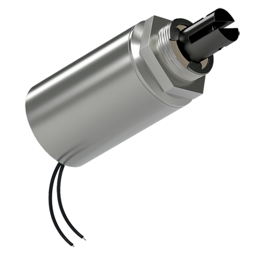
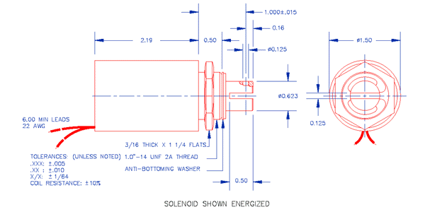
Quantity adjustment on next page Series S-22-150 Optional Plunger Return Spring: SP30 and SP31  If the internal wire gauge for winding is predetermined or if the "voltage" is different from the above, enter the desired information in the above box labeled "Special Comments" and select the closest "voltage" and "duty cycle". C = Continuous (100%) Duty Cycle, Maximum On-Time = Infinite Approximate Input Power = 10 Watts Force at 0.10" (2.5 mm) stroke: 92.0 Oz (2608 gr) Force at 0.50" (12.7 mm) stroke: 11.0 Oz (312 gr) Force at 1.00" (25.4 mm) stroke: 2.0 Oz (57 gr) I = Intermittent (50%) Duty Cycle, Maximum On-Time = 580 Seconds Approximate Input Power = 20 Watts Force at 0.10" (2.5 mm) stroke: 165.0 Oz (4678 gr) Force at 0.50" (12.7 mm) stroke: 22.0 Oz (624 gr) Force at 1.00" (25.4 mm) stroke: 2.5 Oz (71 gr) L = Long Pulse (25%) Duty Cycle, Maximum On-Time = 210 Seconds Approximate Input Power = 40 Watts Force at 0.10" (2.5 mm) stroke: 218.0 Oz (6180 gr) Force at 0.50" (12.7 mm) stroke: 39.0 Oz (1106 gr) Force at 1.00" (25.4 mm) stroke: 6.5 Oz (184 gr) P = Pulse (10%) Duty Cycle, Maximum On-Time = 56 Seconds Approximate Input Power = 100 Watts Force at 0.10" (2.5 mm) stroke: 330.0 Oz (9356 gr) Force at 0.50" (12.7 mm) stroke: 110.0 Oz (3119 gr) Force at 1.00" (25.4 mm) stroke: 20.0 Oz (567 gr) Tubular Solenoid, Pull type, 1.50" (38 mm) DIA X 2.19" (56 mm) L. Mounting: Threaded front end and matching 1"-14 nut. Minimum Heat Sink: Equivalent of 6.0" x 6.0" x 0.125" (152 mm x 152 mm x 3.2 mm) Aluminum Plate All values are at 25ºC. Duty Cycle= on time/(on time+off time) in one cycle of operation when voltage is being cycled on and off. V = R × I P = V × I = V² /R = R × I² V = input D.C. voltage (volts) R = solenoid resistance (ohms) I = current used by solenoid (amperes) P = input power to solenoid (watts) Shipping Weight: 1.6 lb (0.7 kg) Quantity adjustment on next page 
|
Copyright © ElectroMechanicsOnline.com


